Integrated Survey, Design and CAD
 MicroSurvey CAD Premium contains all the survey calculations, design, and drafting functionality that we have at MicroSurvey Software Inc. There is no need to load additional modules or buy them. With MicroSurvey CAD Premium you have a full toolbox. Everything from downloading your data collector to plotting a finished drawing is included.
AutoCAD Compatible: MicroSurvey CAD is compatible with AutoCAD files
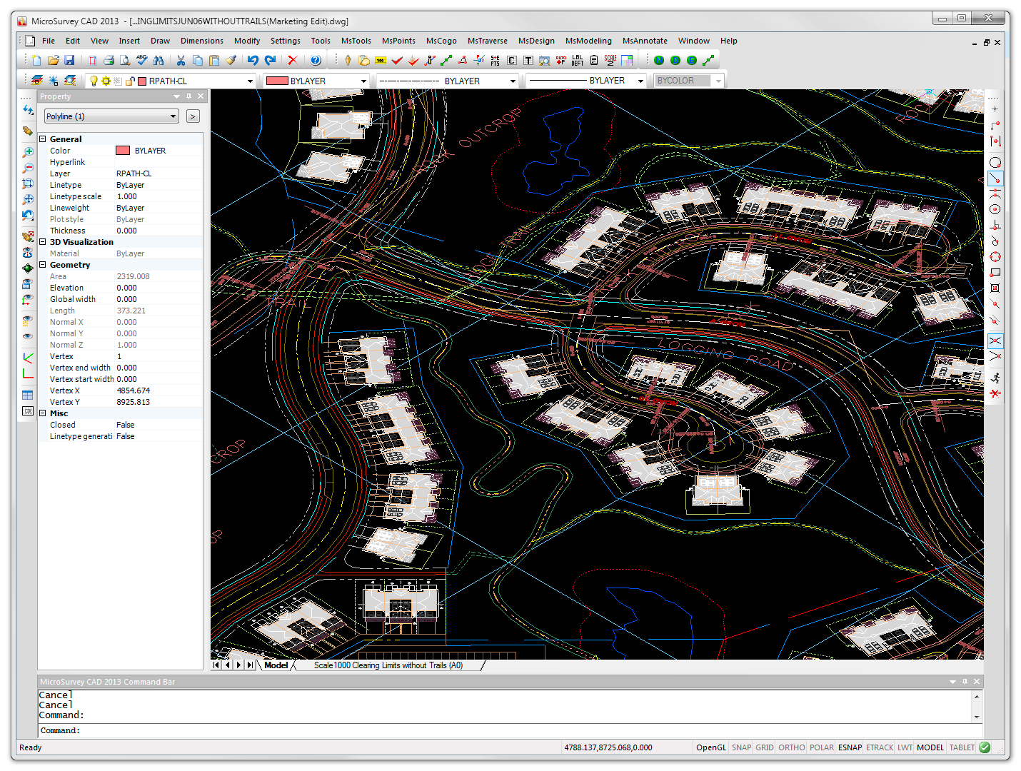
An integrated program needs the ability to read standard drawing files. With MicroSurvey CAD all your files are stored in industry standard .dwg format. No conversions are necessary. Our Project Manager displays the drawing preview for .dwg files so you can see the contents before you open the file. The program will round trip all custom proxy objects that may have been added to the drawing by non-standard software. No data is lost by opening in MicroSurvey CAD and re-saving the drawing. Everything is maintained in the .dwg file that was originally there. In order to maintain compatibility with standard AutoCAD, MicroSurvey does not create any custom proxy objects in the DWG file. Every entity that is created by MicroSurvey CAD can be manipulated by any standard AutoCAD® version.Shape Files, Fonts, Linetypes, Hatch Files All Work Fine
MicroSurvey CAD can utilize shape files, fonts, linetypes, and hatch files from AutoCAD. This means that if you have a custom shx font file in your AutoCAD installation, you can use it in your MicroSurvey CAD installation. The fonts will look the same. MicroSurvey CAD also reads and writes DXF files in case you need to go to a non-AutoCAD product.Powerful Survey, Geodetic and Geospatial Data Routines
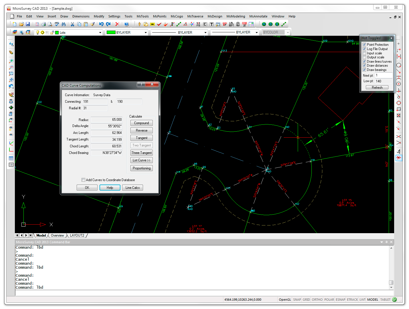
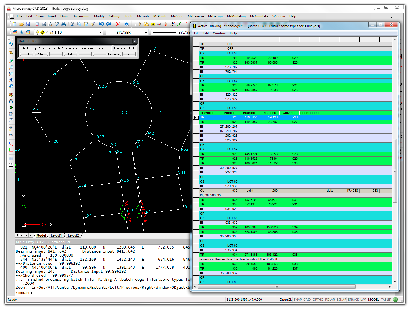 Record all of your COGO entries with Batch and replay as desired. MicroSurvey CAD includes a powerful set of COGO functions. Our new Batch COGO capability is unmatched. As part of Active Drawing Technology, it allows you to build complex COGO calculations in a spreadsheet and re-run them as necessary. MicroSurvey CAD also includes command line COGO that you can use at any time by simply typing “COGO” at the prompt. You immediately enter a familiar style of entry that prompts for point numbers, bearings, distances, and solve points. Intersections are computed by leaving unknowns blank, and letting the program automatically determine what type of intersection you would like to compute. Bearings, distances, point numbers can all be picked off the screen by selecting point labels or lines. COGO commands are also available in a more graphical format. If you select a line or arc on the screen with no command running, you can immediately calculate new points. MicroSurvey CAD also allows you to compute without storing point numbers. The lines and arcs that you create can be instantly coordinated and numbered at a later time. Helmerts Transformation. With the Helmert’s Transformation, you are able to rotate, shift and scale up to thousands of points based upon a best fit solution using 2 to 500 pairs of common coordinate points, all with the execution of a single command! When more than two points are common in each system, redundancy exists and a Least Squares method is used to determine the optimum (best-fit) transformation parameters. Coordinate Transformations. Use the coordinate transformation function to easily transform your data from one system to another. UTM, 3TM, SPC (NAD27, NAD83, HARN) and hundreds of others are supported. Other Tools. A Proportioning function makes it easy to proportion distances along arcs or curves, to create equal line divisions and divisions based on ratios like dividing a line into 2 segments 1 segment at 2/3 of the overall distance and the other at 1/3. Radial Inversing can be used to create radial field ties quickly and effectively. List the ties in a line table with the click of a button.
Geospatial Data and Imagery
- Enhance your drawing with geospatial data and imagery, loaded from local files or streamed from online sources.
- Powered by Blue Marble Geographics’ Global Mapper SDK v15.
- Over 150 supported file formats including Raster Images, Shapefiles, LiDAR, GeoPDF, GeoTIFF, Microstation DGN, ASCII Coordinates, ESRI, ERDAS, Garmin, KML, COLLADA, Sketchup, and many many many more…
- Stream online imagery from any WMS (Web Map Service), WCS (Web Coverage Service), OSM (OpenStreetMap Tiles), Google Maps Tiles, TMS (Tile Map Service), WFS (Web Feature Services), or WMTS (tiled WMS) source.
- Select MsTools > Global Mapper from the menus, or type GLOBAL_MAPPER at the command line.
Store & Edit Geodetic Position
- Store & Edit the geodetic position of grid points using a new dialog with the same look-and-feel as the standard Store & Edit Points command.
- Edit the Latitude, Longitude, Elevation, Description, Note, etc for each point.
- View the Northing and Easting for each point (read-only).
- View the Combined Scale Factor for each point (read-only).
- View the Convergence Angle for each point (read-only).
Identify Geodetic Position
Identify the geodetic position (including the Latitude, Longitude, Combined Scale Factor, and Convergence Angle) of grid points by clicking in your drawing.Label Geodetic Position
Label the geodetic position (including the Latitude, Longitude, Combined Scale Factor, and Convergence Angle) of grid points in your drawing, with customizable format and precision options.Coordinate System Search
- Search for appropriate coordinate systems, based on a specified latitude/longitude position.
- Select your appropriate system from the search results, and instantly set it as your drawing’s Coordinate System.
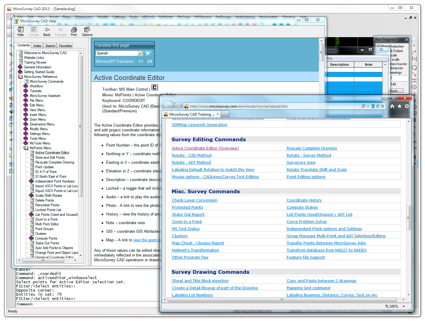
Active Coordinate Editor: Coordinate Systems
- You can now view columns showing the Combined Scale Factor for each coordinate. You can now view columns showing the Convergence Angle for each coordinate.
- You can now view columns showing the Elevation for each transformed coordinate.
- The Coordinate Systems dialog has been reworked to make it more intuitive and easier to use.
Complete Traverse or Network Adjustments
 MicroSurvey CAD supports a full range of Traverse Adjustment Tools:
A full 3D least squares adjustment can be done if there is redundancy in your traverse network. It is fully integrated to directly read MicroSurvey traverse files, sort the observation data, compute adjusted coordinate values for all points (including sideshots) and update your drawing database. The program supports adjustment in 1, 2 or 3 dimensions and provides three levels of reporting, complete with statistical analysis. This is just the tool you need for computing closed traverse networks that are not easily balanced using traditional methods. Integrated in the adjustment package is blunder detection, published instrument errors, graphical elipse display, reprocessing and network pre-analysis. Watch a movie here.Angle Balance
Active Drawing Technology
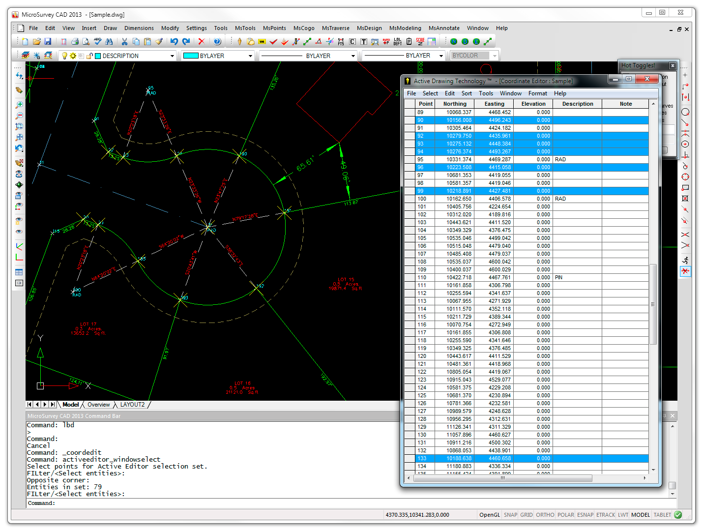 Active Coordinate Editor
Dynamically view and edit coordinate data with changes reflected immediately in both the coordinate editor window and in the drawing window. MicroSurvey CAD operates intuitively: selecting a point in the drawing will open the editor and highlight that coordinate in the editor automatically. Alternatively, selecting a coordinate in the editor will zoom to that point in the drawing.
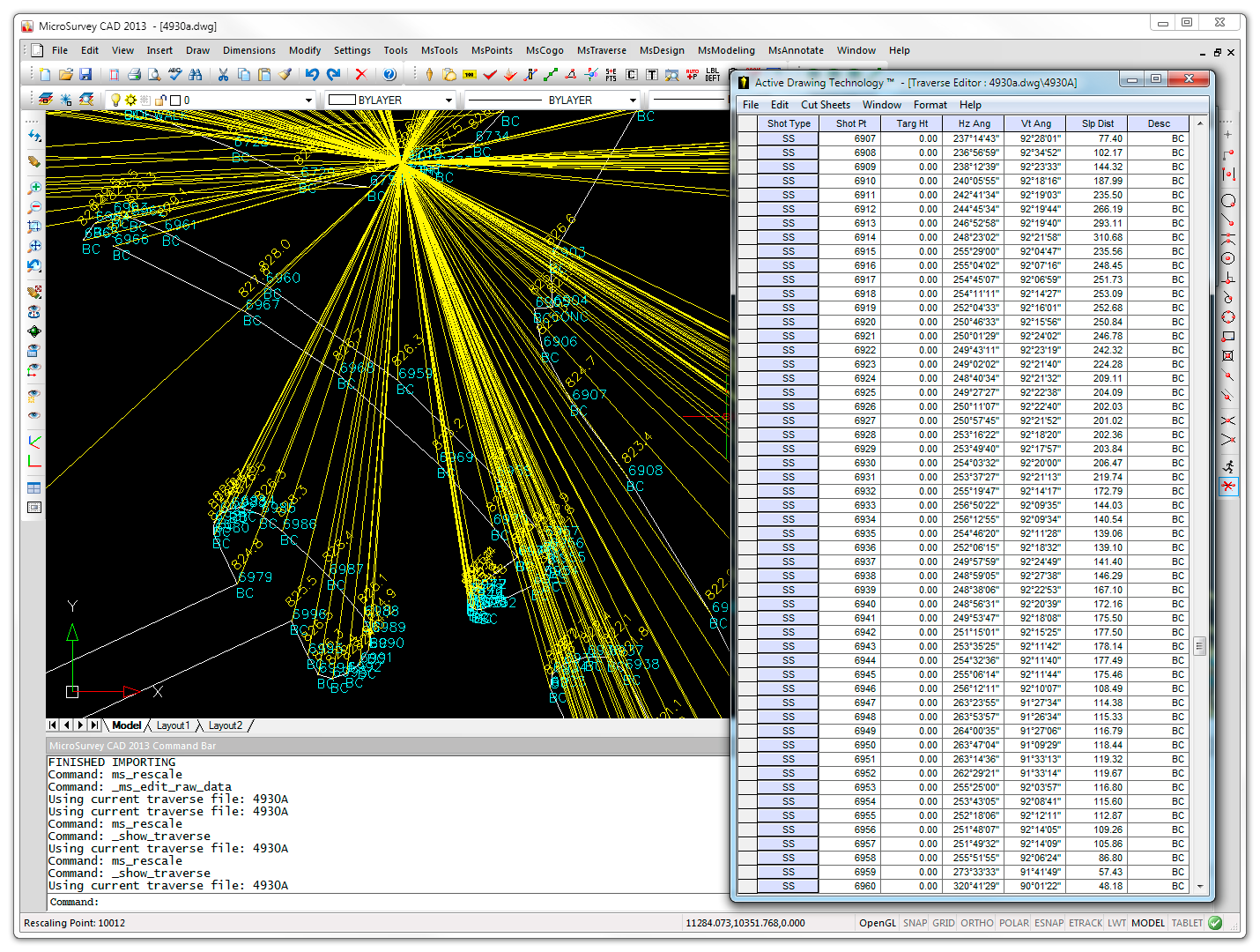
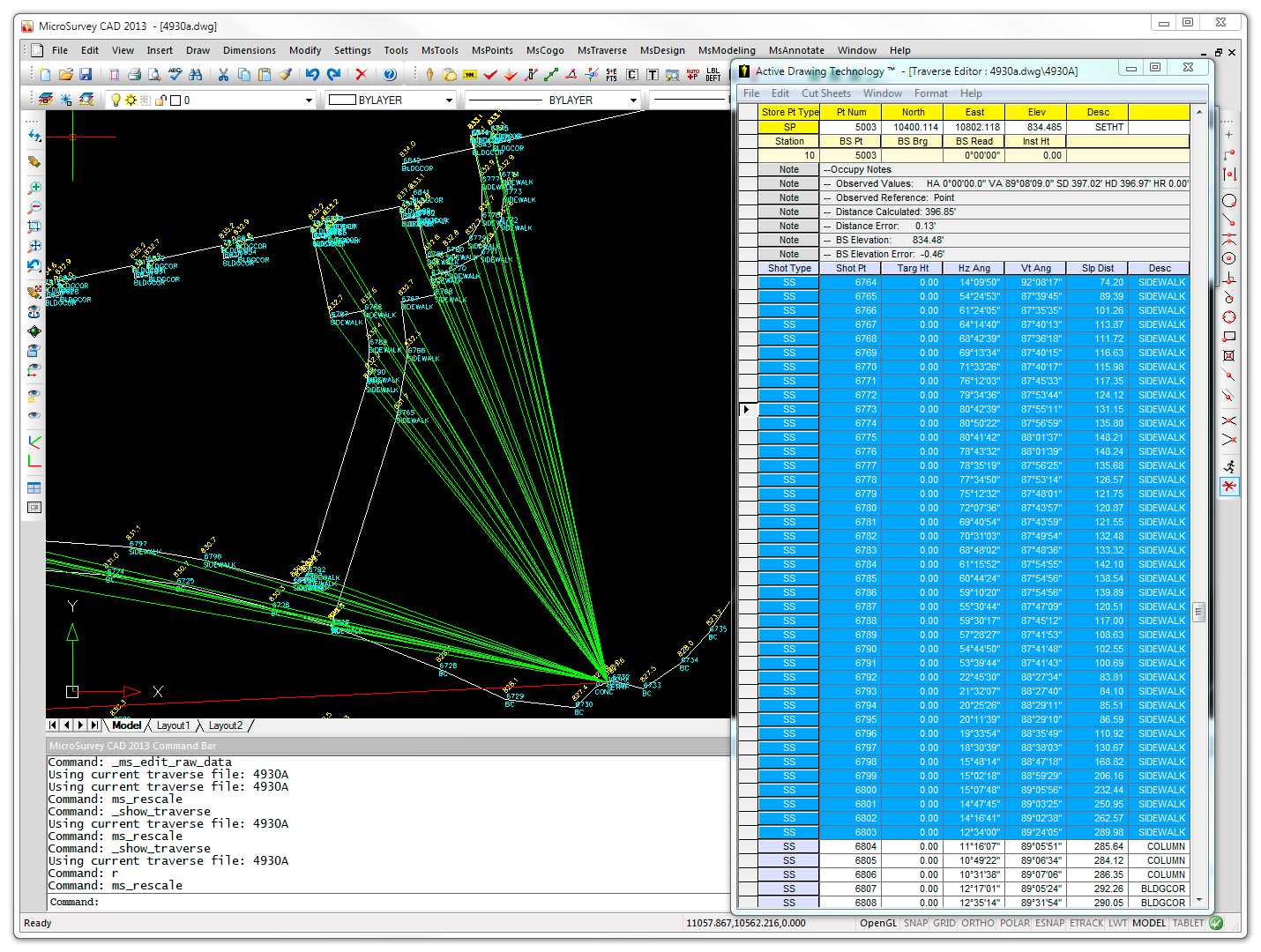
Active Traverse Editor
Verifying and editing your raw data is now much faster and allows for painless correction. Traverse data is represented in a smart, spreadsheet-like editor that has incredible drag and drop capabilities. The Active Traverse Editor allows you to not only work with your raw data at any point in the traverse quickly, but it also allows customization of the views available and opens multiple traverse data sets simultaneously. Errors in your traverse data are amazingly easy to spot and fix.
Active Batch COGO
Batch COGO is a system for data entry and calculation that allows you to browse an entire COGO entry history, quickly identify errors and easily make changes. At any point, COGO entries can be edited and reprocessed with the correction immediately reflected in the drawing. What’s more, the interface is built with smart tags for data types like Traverse, Bearing-bearing intersection, Distance-distance intersection and more. MicroSurvey’s Active Batch COGO is like nothing else on the market!
Advanced Features
Inside the active coordinate editor window you can choose to display geodetic positions, ellipsoid and orthometric heights, convergence angles and combined scale factors for your points.
Active Coordinate Editor
Dynamically view and edit coordinate data with changes reflected immediately in both the coordinate editor window and in the drawing window. MicroSurvey CAD operates intuitively: selecting a point in the drawing will open the editor and highlight that coordinate in the editor automatically. Alternatively, selecting a coordinate in the editor will zoom to that point in the drawing.
Active Traverse Editor
Verifying and editing your raw data is now much faster and allows for painless correction. Traverse data is represented in a smart, spreadsheet-like editor that has incredible drag and drop capabilities. The Active Traverse Editor allows you to not only work with your raw data at any point in the traverse quickly, but it also allows customization of the views available and opens multiple traverse data sets simultaneously. Errors in your traverse data are amazingly easy to spot and fix.
Active Batch COGO
Batch COGO is a system for data entry and calculation that allows you to browse an entire COGO entry history, quickly identify errors and easily make changes. At any point, COGO entries can be edited and reprocessed with the correction immediately reflected in the drawing. What’s more, the interface is built with smart tags for data types like Traverse, Bearing-bearing intersection, Distance-distance intersection and more. MicroSurvey’s Active Batch COGO is like nothing else on the market!
Advanced Features
Inside the active coordinate editor window you can choose to display geodetic positions, ellipsoid and orthometric heights, convergence angles and combined scale factors for your points.
Smart Information
 Picking on objects in the drawing will automatically invoke commands based on the objects that are picked. For instance, picking on a line will bring up the CAD Lines dialog where you can review the starting and end points of the line, slope, change in elevation and more.
Other smart objects that have this type of functionality are curves, text and points. Picking on a point will start the Active Point Editor and allow you to browse the entire coordinate database. MicroSurvey makes it easy to get at the information you need by simply picking on the objects in the drawing. What could be easier?
You can also switch to a 2D mode that will draw all your entities at elevation zero while retaining it’s true elevation in the point database.
Picking on objects in the drawing will automatically invoke commands based on the objects that are picked. For instance, picking on a line will bring up the CAD Lines dialog where you can review the starting and end points of the line, slope, change in elevation and more.
Other smart objects that have this type of functionality are curves, text and points. Picking on a point will start the Active Point Editor and allow you to browse the entire coordinate database. MicroSurvey makes it easy to get at the information you need by simply picking on the objects in the drawing. What could be easier?
You can also switch to a 2D mode that will draw all your entities at elevation zero while retaining it’s true elevation in the point database.
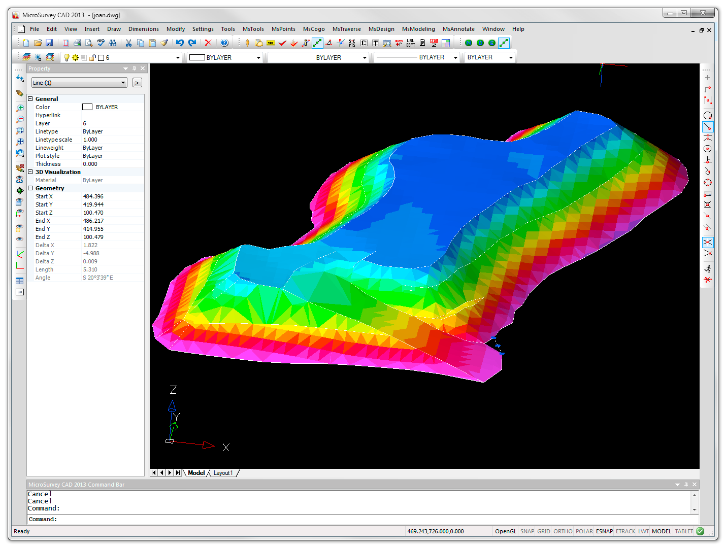
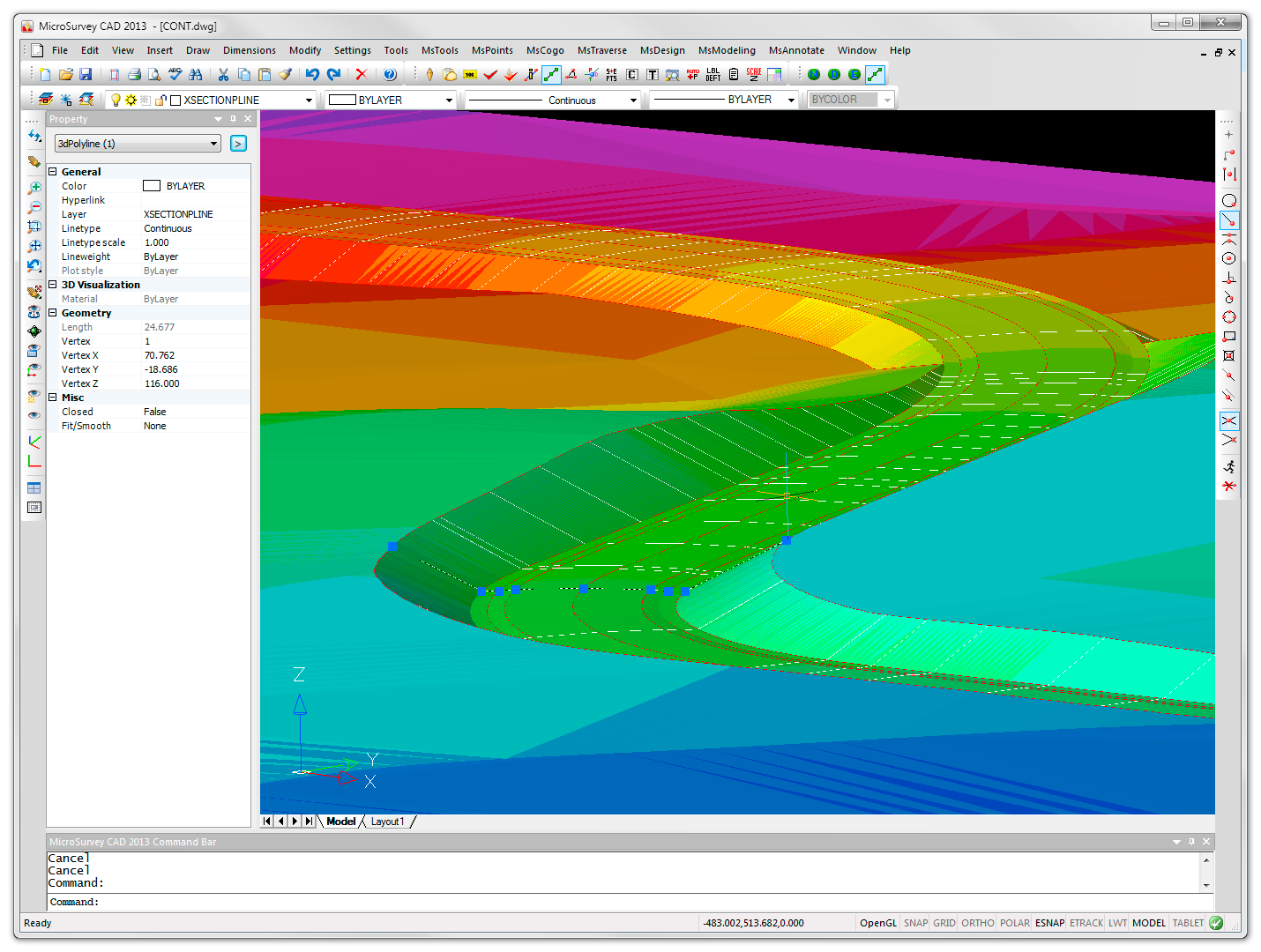
Powerful DTM Contouring/Modeling Volumes (Premium Only)
 As part of a complete package, MicroSurvey CAD creates surface models at lightning speed. With very fast modeling engines, you can manipulate surfaces by adding or removing points, work with breaklines, and create boundaries. We stopped testing triangulation speed when it broke through the 100,000 points per second level.
Volumes are computed fast and easy between multiple surfaces, or between a surface and a specific elevation. Multiple area volumes can be computed simultaneously by defining boundaries. These act like a “cookie cutter” to slice vertically through surfaces to get specific volumes.
Visualization in MicroSurvey CAD is unmatched with fast 3D rendered views of TINS, Grids, and Triangulated Grids (a more accurate method of representing a surface).
Cross sections or Profiles are just a click a way.
As part of a complete package, MicroSurvey CAD creates surface models at lightning speed. With very fast modeling engines, you can manipulate surfaces by adding or removing points, work with breaklines, and create boundaries. We stopped testing triangulation speed when it broke through the 100,000 points per second level.
Volumes are computed fast and easy between multiple surfaces, or between a surface and a specific elevation. Multiple area volumes can be computed simultaneously by defining boundaries. These act like a “cookie cutter” to slice vertically through surfaces to get specific volumes.
Visualization in MicroSurvey CAD is unmatched with fast 3D rendered views of TINS, Grids, and Triangulated Grids (a more accurate method of representing a surface).
Cross sections or Profiles are just a click a way.
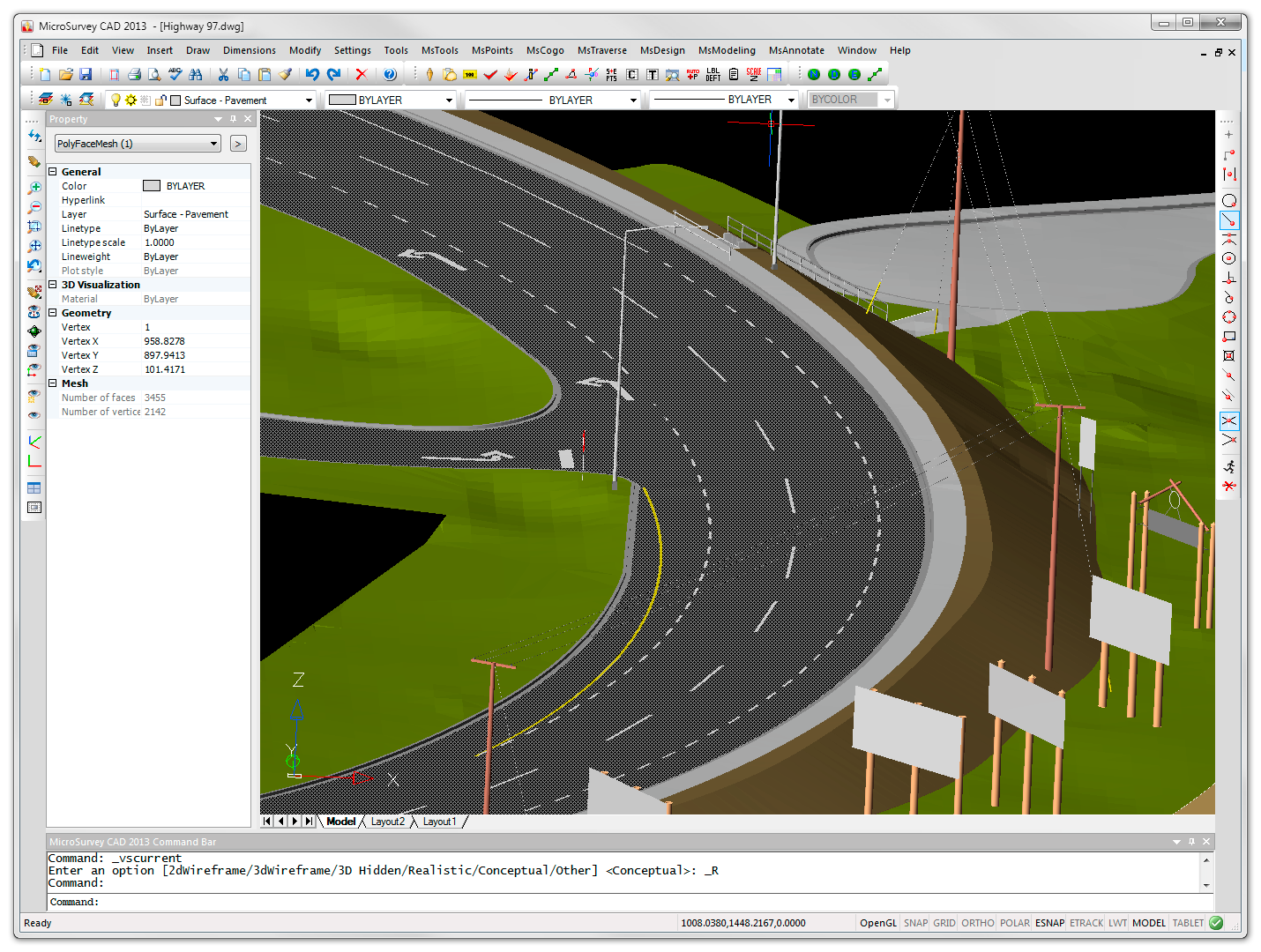
Complete Site Design
 MicroSurvey CAD’s Road Design Wizard makes creating a 3D road along a horizontal and vertical alignment a snap. Creating templates is easy with our graphical template editor. Multiple passes can be made down a road with various templates to create a multi-level surface.
Site design for ponds, building sites, canals, ditches, or slopes is as easy as 1-2-3. Select your border polylines and apply slopes. Our system automatically calculates all the intersections and creates new surfaces in one command. Volumes fall right out automatically once you have the site.
Tools are available to slice the surface along spaced cross sections and plot all the results automatically.
MicroSurvey CAD’s Road Design Wizard makes creating a 3D road along a horizontal and vertical alignment a snap. Creating templates is easy with our graphical template editor. Multiple passes can be made down a road with various templates to create a multi-level surface.
Site design for ponds, building sites, canals, ditches, or slopes is as easy as 1-2-3. Select your border polylines and apply slopes. Our system automatically calculates all the intersections and creates new surfaces in one command. Volumes fall right out automatically once you have the site.
Tools are available to slice the surface along spaced cross sections and plot all the results automatically.
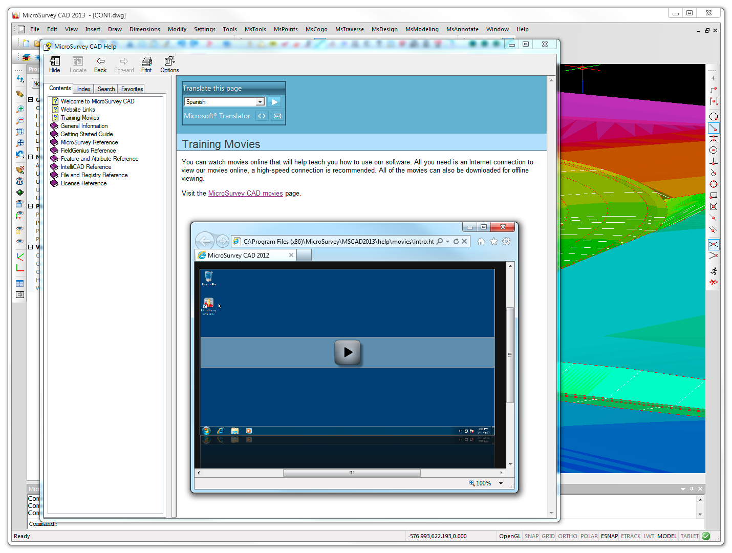
Learning Resources
 Over twelve hours of training movies (more than 170) are included. To quote Joe Bell from Professional Surveyor Magazine, “If you forget how to do something, you do not have to run to the office guru or spend hours going through the manual trying to find out how to do what you want to do. You just go to the movies-the ones in the Help files, that is…you have access to 123 neatly arranged movies that tell and show you exactly what you have to do”.
Also included is the most modern help system available – with a fully indexed, linked help file that exactly models the layout of the pulldown menus. It could not be easier to find items than to see them exactly ordered the same as the menus. The movies play right inside the help system. It is the easiest method of learning software.
A complete description of all the CAD drawing and editing commands is included in the help system. Many commands in both the surveying and drafting sections have direct movie links.
Documentation is also provided for one of the extra bonus values in using MicroSurvey CAD – Lisp programming! Lisp is an easy language to master, and with lisp you have even more control over the CAD engine. MicroSurvey provides a lisp interface to the coordinate database, so you can write simple routines do import or export in your own desired format, or perform custom calculations between coordinate points.
Over twelve hours of training movies (more than 170) are included. To quote Joe Bell from Professional Surveyor Magazine, “If you forget how to do something, you do not have to run to the office guru or spend hours going through the manual trying to find out how to do what you want to do. You just go to the movies-the ones in the Help files, that is…you have access to 123 neatly arranged movies that tell and show you exactly what you have to do”.
Also included is the most modern help system available – with a fully indexed, linked help file that exactly models the layout of the pulldown menus. It could not be easier to find items than to see them exactly ordered the same as the menus. The movies play right inside the help system. It is the easiest method of learning software.
A complete description of all the CAD drawing and editing commands is included in the help system. Many commands in both the surveying and drafting sections have direct movie links.
Documentation is also provided for one of the extra bonus values in using MicroSurvey CAD – Lisp programming! Lisp is an easy language to master, and with lisp you have even more control over the CAD engine. MicroSurvey provides a lisp interface to the coordinate database, so you can write simple routines do import or export in your own desired format, or perform custom calculations between coordinate points.
Customizable Interface and Commands
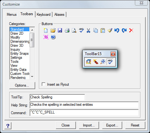 More than any other program, MicroSurvey CAD allows you to customize your own work area. Toolbars, menus, screen areas, and command line placement can all be controlled by you.
Toolbars: The new toolbar editor is simple. Edit existing toolbars, or create a new one. Just drag a button into empty space and you immediately have a new toolbar.
Menus: We include a graphical menu editor that allows you to cut and paste different menus together, remove sections to streamline the menus for your own use, or create entirely new menus for specific types of jobs.
Lisp Programming: Unlike other surveying packages, our program supports your own lisp programs. You can run Autolisp programs that run on the command line or even sophisticated versions that use DCL dialog boxes. With our lisp programming extensions, you can read and write to the coodinate database directly from lisp programs.
Screen Areas: You can turn on and off the command line, the properties toolbar, and the status line. These all can be toggled quickly to maximize your drawing window for more productivity.
Layout: You control whether you want the Command Line at the top or bottom, whether you want to see a side menu area, and how you want multiple windows to appear.
More than any other program, MicroSurvey CAD allows you to customize your own work area. Toolbars, menus, screen areas, and command line placement can all be controlled by you.
Toolbars: The new toolbar editor is simple. Edit existing toolbars, or create a new one. Just drag a button into empty space and you immediately have a new toolbar.
Menus: We include a graphical menu editor that allows you to cut and paste different menus together, remove sections to streamline the menus for your own use, or create entirely new menus for specific types of jobs.
Lisp Programming: Unlike other surveying packages, our program supports your own lisp programs. You can run Autolisp programs that run on the command line or even sophisticated versions that use DCL dialog boxes. With our lisp programming extensions, you can read and write to the coodinate database directly from lisp programs.
Screen Areas: You can turn on and off the command line, the properties toolbar, and the status line. These all can be toggled quickly to maximize your drawing window for more productivity.
Layout: You control whether you want the Command Line at the top or bottom, whether you want to see a side menu area, and how you want multiple windows to appear.
Quality Tools for Excellent Value
 Possessing features normally found only in expensive AutoCAD based systems, MicroSurvey CAD is approximately one third of the price of more expensive solutions.
Having a completely integrated solution means more productivity. No switching menus between different modules. No need to order additional software to get the job done. We put everything that we know into MicroSurvey CAD Premium.
USB Security Key Licensing: MicroSurvey’s flexible licensing system allows your software license to move. With our USB Security Key, you can run a single MicroSurvey license at home, the office, and in the field. Another benefit is the ability to share a license with co-workers. Share 3 licenses between 5 people by just moving USB keys.
Network Licensing: With our network floating license option, you only need to purchase as many seats as your staff will use. Our system allows you to specify a location for the floating license USB Security Key, and user systems will check to see if licenses are available. Nothing needs to be installed on your main server. We are careful what we install on our servers too. Any machine in the office can have the key installed and it will supply licenses to other user machines.
Possessing features normally found only in expensive AutoCAD based systems, MicroSurvey CAD is approximately one third of the price of more expensive solutions.
Having a completely integrated solution means more productivity. No switching menus between different modules. No need to order additional software to get the job done. We put everything that we know into MicroSurvey CAD Premium.
USB Security Key Licensing: MicroSurvey’s flexible licensing system allows your software license to move. With our USB Security Key, you can run a single MicroSurvey license at home, the office, and in the field. Another benefit is the ability to share a license with co-workers. Share 3 licenses between 5 people by just moving USB keys.
Network Licensing: With our network floating license option, you only need to purchase as many seats as your staff will use. Our system allows you to specify a location for the floating license USB Security Key, and user systems will check to see if licenses are available. Nothing needs to be installed on your main server. We are careful what we install on our servers too. Any machine in the office can have the key installed and it will supply licenses to other user machines.

Quick Links
[wbcr_php_snippet id="221056"]
About Us
About Us
© 2019 MicroSurvey Software Inc. All rights reserved